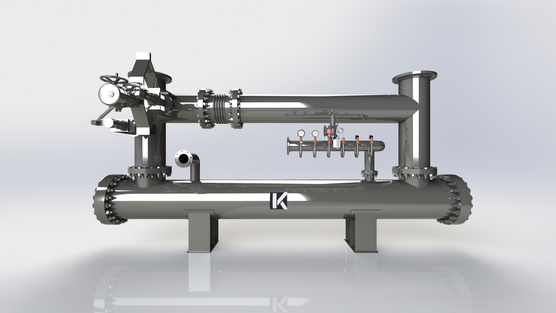
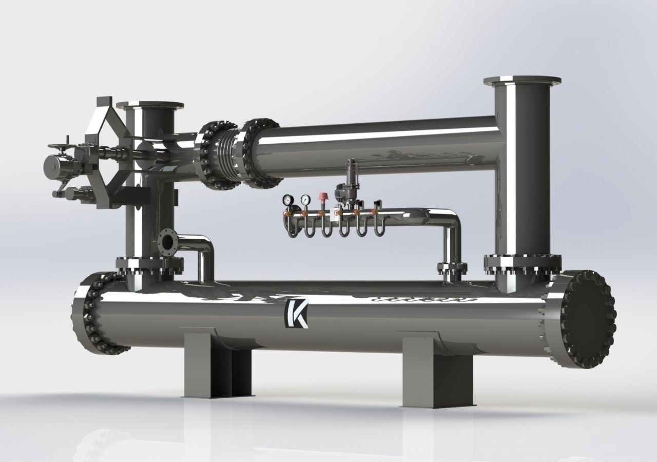
Exhaust gas is a gas produced by the combustion of fuels in solid, liquid or gaseous phases and released into the atmosphere through a duct. The gases produced as a result of the combustion reaction are generally CO (carbon monoxide), N2 (nitrogen), NOx (nitrogen oxides), CO2 (carbon dioxide), H2O (water vapor), hydrocarbons, some unburned fuel and particles depending on combustion efficiency.
Exhaust gas contains a serious energy with the heat generated as a result of combustion. With the exhaust gas heat exchangers to be used in this field, energy can be recovered before it is discharged into the atmosphere and used for heating a fluid to be used in the process or for district heating by heating closed cycle water. If integrated into an engine-operated generator set, it can be converted into CHP (combined heat and power), greatly increasing overall efficiency.
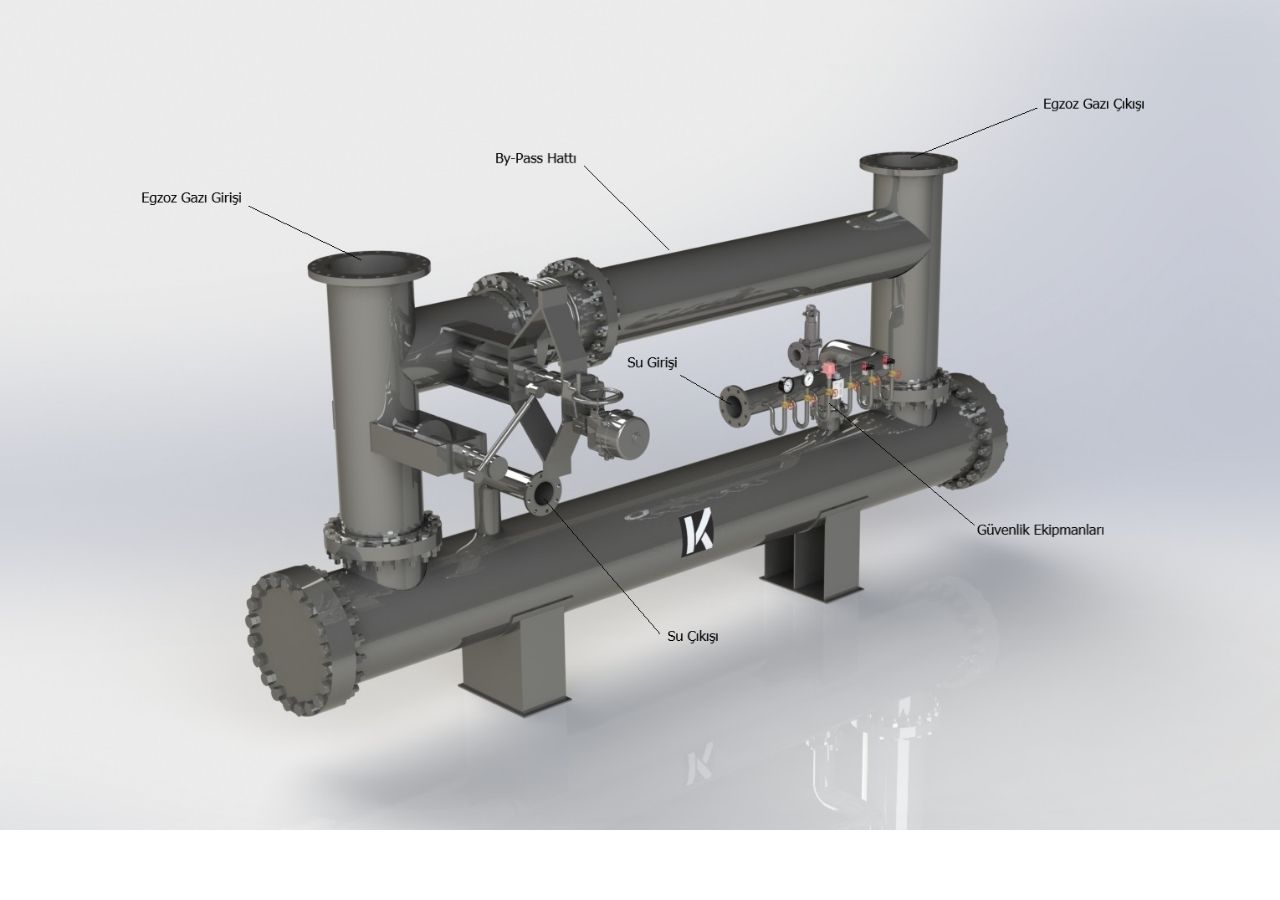
The exhaust gas passes through the tube bundle, which is the primary circuit of the exchanger. At the same time, water circulates around the pipes in the body of the heat exchanger to cool the exhaust gas. Most of the heat in the gases is transferred to the water and the relevant energy is recovered. The design data is obtained from the customer and the thermal and mechanical design of the relevant exchanger is made. It is important to specify the exhaust gas flow rate from these design data in kg/h. Because the volumetric flow rate varies depending on the changing pressure and temperature conditions due to the fact that the exhaust gas generated due to the relevant combustion efficiency is a mixture and it misleads the designer by reaching approximate results as a result of the relevant calculations.
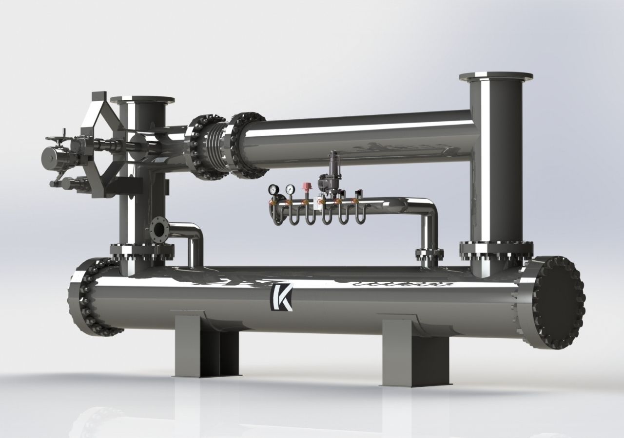
Each of these gases in a volume has a partial pressure. The sum of these partial pressures equals the total pressure of the mixture gas. These partial pressure differences associated with temperature condense due to temperature and pressure drop. A high amount of condensation in the exchanger damages the pipes used and causes contamination inside. Considering this, attention should be paid to the amount of energy recovery to be obtained. To prevent this condensation, exhaust gas should not be allowed to drop below 120˚C (180˚C for diesel power generators).
The relevant exhaust gas is at temperatures of 500˚C and above. If the exhaust gas is delivered to the heat exchanger as a by-pass independent process of the water circuit, it will seriously damage the tube bundle. Before this circuit is switched on, the water circuit in the heat exchanger must be completely filled in the body part and must be in a position to continue flowing. In addition, automatic motor shutdown equipment must be used in conjunction with temperature probes to be included on the heat exchanger. After the exhaust gas circuit is closed, the water circuit must continue to operate for some time to completely remove the heat from the tube bundle from the heat exchanger. Address
Both of the water inlets of the exchanger must be in the vertical position and positioned on the upper side of the exchanger. The aim here is to prevent natural flow and to keep the heat exchanger full of water even if the entire interior of the body is not in operation.
Except for the pressure and temperature limits to be positioned on the heat exchanger, a safety valve to be set in accordance with the process must be used for flow control and unwanted pressure increases in the installation. In addition, when the heat exchanger is first commissioned, automatic air discharge purifiers used at certain points on the installation should be positioned in order to discharge the air in it. The air remaining in the heat exchanger or installation causes bubble formation. This bubble formation damages the material and causes a decrease in heat exchanger efficiency.
Another important issue is the exhaust gas pressure drop. Since the exhaust gas coming out here will be reused in the heating of fresh air, especially in engines, the pressure losses in the heat exchanger must be designed in accordance with the maximum allowable pressure loss condition to be taken by the engine manufacturer. In addition, the pressure loss criterion that will occur in the silencer must not be ignored in the design process.